It should be a very clear distinction made here, which, at first glance, is a source of serious confusion. The display of a symbol involving two different
elements:
The data contained in the DDRAM is an 8-bit code, which has been sent from 'the host controller bus.
It is handled automatically by the controller as if it were an input address
of the characters generator; for each address, the CG makes out the 40 bits that form the matrix of character.
The table describes the correspondence between addresses and contents of the character generator ROM is present in the data sheet of the controller.
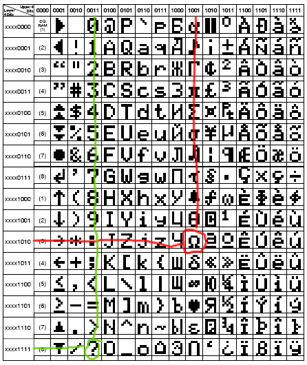 |
This side is the character set A02 Controller HD44780.
Addresses 10h to FFh input match letters, numbers and symbols ASCII characters as well as non-European alphabets, accented letters, various
symbols.
Then, by sending, for example, the code 9Ah as given, it will serve to route a cell of CG where is the matrix of points of the character omega minuscule, which will be displayed; sending the data 3Fh will display the question mark symbol.
But if we send given as a value between 00h and FFh?
In the table, these values have no corresponding character, given that they are deflected to the CGRAM, where correspond to characters introduced by
'user. |
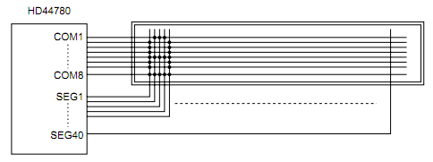
The 40-bit output from the CG are prepared by the controller on its lines COM and SEG which control respectively rows and columns of the LCD panel
and forming the symbol, which is presented in a well defined area of the display.
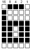 |
A 5x8 character has as a basis this matrix.
The points visible to 'cross between rows and columns, can be dark on a light background (typical of models not backlit) or light on a dark background (typical panel with
backlight).
In any case, if the bit is sent to 1, the point at 'junction will be switched on, while the others will remain invisible. For example, in the figure, the figure 6 is presented by the 40 points of the first row which has just three lit, the second and the third one, all the fourth, and so on. |
8 lines being necessary to form a character, it will take 5 to 8 locations of ROM bits each.
Nell 'example, the contents of the 8 cells will be:
| Location |
Dots |
Content |
| binary |
hex |
| 1 |
0 |
1 |
1 |
1 |
0 |
01110 |
0Eh |
| 2 |
1 |
0 |
0 |
0 |
0 |
10000 |
10h |
| 3 |
1 |
0 |
0 |
0 |
0 |
10000 |
10h |
| 4 |
1 |
1 |
1 |
1 |
1 |
11111 |
1Fh |
| 5 |
1 |
1 |
|
1 |
1 |
11011 |
1Bh |
| 6 |
1 |
1 |
|
1 |
1 |
11011 |
1Bh |
| 7 |
1 |
1 |
1 |
1 |
1 |
11111 |
1Fh |
| 8 |
0 |
0 |
0 |
0 |
0 |
00000 |
00h |
User 's the process of transformation from a given image on the LCD panel is transparent and limited only to the DDRAM write the 8-bit code symbol to represent.
From the data sheet of the controller 's user can know the correspondence between data sent and received symbol, and indeed, if the symbol you want is an ASCII character, usually tables match GTC are the main alphanumeric characters with the corresponding ASCII value standard, making it easier to maximum writing on the display. So, for example, wanting to write on the display the symbol now seen, will suffice:
movlw '6'
; ASCII '6' - 36h
call senddatatolcd
The conversion points, sending points to 'LCD, timings, etc.. are all operations that the controller takes place in a transparent manner for the user.
Really comfortable, so as to make these LCD modules the name of "intelligent display".