Dot matrix LCD : the CGRAM
|
Dot-matrix LCD.
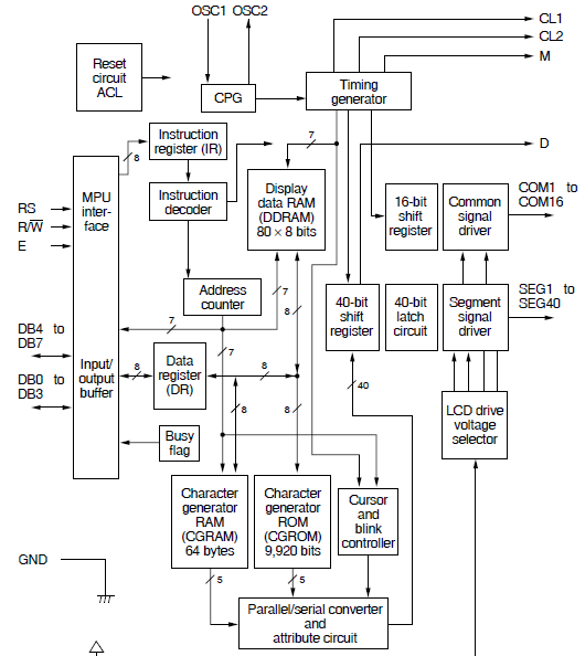
First, let us review the internal structure of the controller that manages the LCD module:
From the block diagram we see that the integrated circuits of the genus HD44780 have three different memory areas:
- CGROM, characters generator in ROM (read only memory, non-erasable)
- CGRAM, characters generator in RAM, readable and writable memory
- DDRAM, memory that matches the characters on the display
Some compatible controllers implement an additional memory area:
- SEGRAM, programmable area for segment icons
All these controllers, however, manage characters in the format 5x8 or 5x11 points (5 columns x 8 lines or 11 lines), whose matrices are available in the character generator in ROM (CGROM).
The procedure for presenting a character on the display consists of a few simple
actions:
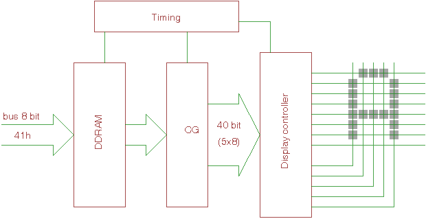
- The controller, via the data bus (DB0-DB7) receives from 'host a hexadecimal code that is placed in an input buffer. The state of the line RS determines whether it is a command or a data to display.
- If it is a datum, the code is saved in the DDRAM, the typical capacity of 80 cells of 8 bits each. All or part of these cells, depending on the size of the LCD panel, correspond to the characters
displayed.
- For the actual display, the controller sends the data in the DDRAM as addresses of a character generator (CG), the output of which is composed of 40
bits.
These bits are processed by a system of parallel-serial shift register, that, through the appropriate timings, the controller uses for the ignition of points on the LCD panel. The 40-bit output from the GC are organized as an array of 8 lines and 5 columns. The 1 bits correspond to a point displayed, the zero bits are
blanks.
Below, the character generator uses the ASCII codes, for which bytes 41h input as data, corresponds to the display of a capital
letter.
Thus, the task of writing a character is simply in send data corresponding to the character you want in the DDRAM and the controller takes care of the complex self-management tasks LCD panel. If you want to write to the display, the letter 'A', just the sequence of statements:
movlw 0x41
call senddatatolcd
senddatatolcd is a subroutine that transfers the data from the accumulator to the W DDRAM controller.
During this operation, the lines RS and RW will assume the right level, by communicating to the controller that it is a data
write:
| Command |
Control |
|
Data |
Function |
Execution time |
| Write data to DDRAM |
RS |
RW |
|
D7 |
D6 |
D5 |
D4 |
D3 |
D2 |
D1 |
D0 |
Send a data to DDRAM for display |
37-100us |
| 1 |
0 |
|
data to DDRAM |
As mentioned, the DDRAM has a width of 80 bytes, which corresponds to a character in 'visible area on the LCD panel according to the number of lines and characters per line available.
For example, for a display with 4 lines of 20 characters each, all 80 bytes in memory DDRAM will be visible. In a display of one row to 8 characters, only 8 locations DDRAM will be
displayed.
|