Dot matrix LCD : the CGRAM
|
How CGRAM work.
The operation of the character generator in RAM is entirely analogous to that of the generator in ROM.
The character code is passed to the CGRAM, from which it generates the matrix that will be transferred to the DDRAM and to the display.
Then the CGRAM will have the same logical structure of the CGROM; simply, the contents of the CGROM is fixed and unchangeable and that of CGRAM is determined by
user.
As we saw earlier, a character consists of 8 lines of 5 bits each, which occupies 8 consecutive locations in memory CG.
The CGRAM typically consists of 64 cells by 1 byte each and a group of 8 consecutive cells determines a symbol.
If we want to display an arrow pointing to the 'high, you will need this array:
| Locazione |
Punti |
Contenuto |
| binario |
hex |
| 1 |
0 |
0 |
1 |
0 |
0 |
00100 |
04h |
| 2 |
0 |
1 |
1 |
1 |
0 |
01110 |
0Eh |
| 3 |
1 |
0 |
1 |
0 |
1 |
10001 |
11h |
| 4 |
0 |
0 |
1 |
0 |
0 |
00100 |
04h |
| 5 |
0 |
0 |
1 |
0 |
0 |
00100 |
04h |
| 6 |
0 |
0 |
1 |
0 |
0 |
00100 |
04h |
| 7 |
0 |
0 |
1 |
0 |
0 |
00100 |
04h |
| 8 |
0 |
0 |
0 |
0 |
0 |
00000 |
00h |
So, for the arrow above, if you have to write the sequence of bytes 04h, 0Eh, 11h, 04h, 04h, 04h, 04h, 04h, 00h in 8 consecutive locations of the
CGRAM.
The mechanism that allows the selection of the array in ROM or RAM depends on the value of the byte in the past as an address input.
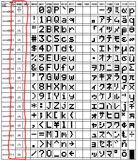 |
We look back to a typical set of characters : this side is the character set A00
of the controller HD44780.
The codes input 10h to 7Fh correspond to letters, numbers and symbols ASCII.
The area between A0h and FFh is occupied by the Japanese simplified characters, letters
of greek alphabet and other symbols.
Address space between 80h and 9Fh is unused and rise to the view of an empty space on the display.
Even the 'area between 10h and 1Fh is unused in this table.
But if we send given as a value between 00h and FFh?
|
In the table, these values have no corresponding character, given that they are deflected to the table of CGRAM, where correspond to characters introduced by
'user.
In other words, the symbols defined by 'user they occupy the first 8 cells of the table: the symbols pre respond fixed in ROM at addresses 10h to FFh and those planned by' user codes will be called between 00h and 07h.
This still allows a match of the first part of the table with the CG ASCII
table
standard, because some of its original values are not symbols printable, but control
characters.
So, from the point of view of the 'use of the special character programmed in CGRAM there is no difference compared to that of a character in CGROM: writing a given towards the DDRAM will give rise to the display of the symbol corresponding to the data itself, depending is are in CGRAM or
CGROM.
Than:
movlw 0x41
call senddatatolcd
produces the presentation of the character A while
movlw 0x02
call senddatatolcd
produces the display of the character 's user has programmed in location 02h of the
CGRAM.

1. - At power on, the controller provides, among other things, to reset the contents of the RAM. Usually it is filled with the character 20h, which corresponds to a space in the ASCII table.
This is to present the display initially empty and ready to receive characters from
'host.
Zeroing of RAM also concerns the CGRAM, for whom it, after the' arrival of the supply voltage, is
empty.
So, in the example above, the box 02h there will be no character
displayed.
Before using the characters in CGRAM need to
write !
2. -And it will be necessary to write them each time that the controller fails' s
power, given that a drop in supply voltage erases the contents of RAM.
3. - Should be noted that, in the case of a RAM, any location can be written, overwritten or read at leisure. So, if you want to use only the character code 02h, you can write the corresponding unused CGRAM leaving all the rest.
On the other hand, having only 8 characters in the 5x8 format, whether at work, more are needed, you must write the data to use, delete one or more of the above.
|
|
