Sometimes need of an indicator for a magnitude of which is not essential to know the value, but if it is
inside of a certain range or below a given limite.
In these cases, a character display (which must be read) would be less effective than some LED (which is immediately appreciable).
In the past We had been made a circuit with classic comparators typically LM311 or LM339, and a quadruple operational, typically LM324, which provided a two-color LED on the following guidelines:
- steady green LED - green low value
- green LED flashing - rising value
- flashing green / red - mean value
- flashing red - high value
- solid red - over limit
In this way, with only one point on which to focus the attention, you can see 5 different situations of tension that can be a divider or a shunt or any sensor or circuit point.
In practice, this kind of indicator is always effective result, despite its simplicity, because it is easy to read and allows the
user a quick evaluation. Situations of flashing, then, attract the attention much more than a numerical indication to read and interpret.
Since we have a voltage input, we can discriminate also the state of charge of batteries, the levels of voltages coming from the pressure sensors or current, but also as an indicator of speed limits, on the output voltage of converters F/V and any other application where it is necessary to identify at first glance the status of a
segnale.
With the actual microcontrollers, with AD converter, a revision of the circuit could only pass from the all-analog to all-digital, with the advantage of a much smaller number of components and the possibility to vary the switching points without need to calculate dividers and resistors have
uncommon values.
The Analogic-Digital Microcontroller.
A practical case can occur with a heat sink for semiconductors, which it is necessary to know if the temperature exceeds a given value, in order to, for example, act on the adjustments or insert a ventilation system.
Given the need to evaluate an analog voltage, use a microcontroller with ADC module, the module that is also available on the tiny PIC 10F series.
In particular, We find it in 10F220 / 22, similar chip that differ only by the available
memory.
We can, of course, use any other microcontroller with ADC, but, since they serve only two pins for the control of the LED and one for the 'input of the voltage to be monitored, the PIC10F 6-pin (4 I / O) are more than adequate , besides having a minimum cost and to occupy a space as never reduced (in the version SOT23-6).
The electrical circuit is, of course, extra simple:
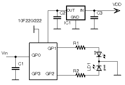 |
IC1 is a common 78L05 for supply a stable voltage to the PIC: this
is indispensable, because the ADC module use the Vdd as Vref for the
conversion.
In this way the circuit can be supplied starting from 7V to over 24V. If you already have a voltage of 5V with a few tens of milliamps, IC1 and C3 may be omitted (but no C2).
C1 100nF
C2 2.2uF-10uF
C3 10uF-100uF
R1/2 220ohm |
IC1 (or a well stabilized Vdd) is essential: even if the PIC is plug-in itself as low as 2V and does not require a particular stability of the Vdd, however, serves a supply voltage accurate and of good quality, since it is the Vref for reading AD, otherwise we will have difficulty in interpreting the results of the conversion.
The ADC module of PIC10F22x is 8 bit and, in a simplified application such as this, the accuracy of the reference voltage provided by a linear three-terminal is sufficient for the conversion. However, if the need to do a conversion to 10 bits 0 12 bits, it would be indispensable to a different microcontroller, provided with input for an external Vref, supplied by a precision voltage reference (LM4040 and the like), in addition to a Vdd low noise.
The LED is a two-color three-pin, with one red and one green; in dependence on the type used, it is necessary to vary the resistances R1 and R2 to achieve the desired brightness, of course not exceeding the limit 25mA of current supplied from the pins of the microcontroller.
The LED indicates to the user the status of the temperature reached, going from green to yellow to red with
the increase of temperature itself, whose situation is of immediate reading. They were laid down the following conditions:
| Temperatura |
LED |
Situazione |
| T<40°C |
Green |
low temperature |
| 40°C<T<50°C |
Green/Yellow blinking |
rising temperatura |
| 50°C<T<60°C |
Yellow |
mean temperature |
| 60°C<T<70°C |
Yellow/Red blinking |
high temperature |
| 70°C<T |
Red |
over temperature |
The "yellow" is those that appears when you switch to green and red with a duty cycle of about 50%.
"yellow / red flashing" is obtained by keeping the red LED and toggling the green; so is the "green / yellow flashing" is obtained by keeping the lights green and switching the red.
The "yellow flashing" is obtained by switching both red and green.
It will be able to easily obtain other effects, by combining the times of switching on and off of the two LEDs.
The operation is simple: the microcontroller reads the voltage to be evaluated and, according to the limits set, controls the switching of the
LEDs.
We can also employ an output for a relay or use a microcontroller with a greater number of I / O for controlling a LED bar and so on.
Software.
Obviously, given the type of chip used, which is a Baseline with minimal resources, the program is in Assembly and is also simple
roll.
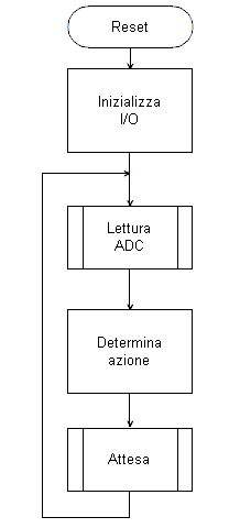 |
The flow chart of the program, even in the case of a simple program like this, is an important element for the programmer, since its drafting allows to have a clear picture of what you want to attract and allows to transform the logical path into instructions in so much easier than if it had been
drawn.
The "active" is essentially a loop recycling at a rate of about 1/4 of a second the
following:
- reading of 'ADC
- evaluation of the results in the table view before control of LED
- timing
The time delay determines the flashing speed. Changing it, they will get different cadences. Since it is a subroutine, it can be replaced with
ease.
|
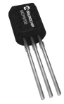
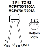
In our case, the voltage to be measured arrive from a cheap sensor active, Microchip MCP9701:
|
|
In particular, the 'output proportional to temperature consists of a voltage that varies from 19.5 mV / ° C.
The component is provided in the classic container TO-92, but also in SOT23 and SC70 for SMD.
It can assess from -40 ° C to + 150 ° C, with an accuracy of ± 2 ° C from 0 to 70 ° C.
|
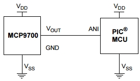 |
It is provided for a direct connection with the 'analog input of the microcontroller and requires no conditioning circuit or linearizations particular in the field of readings expected.
Of course you can use other similar sensors, as MCP9700 or LM35, adjusting the values to which you switch LED status. |
We observe that the resolution of one step of the output value of the AD converter 8-bit, with 5V reference voltage is:
Vstep = Vref / step = 5 / 256 = 0.019531V
which is precisely the 19.5mV provided by the manufacturer. This greatly simplify the software, since it does not need any tuning or complicated calculations.
MCP9701 has an offset at 0 ° C equal to 400mV, which allows it to measure even at temperatures below 0 ° C.
Then, the voltage at a given temperature above 0 ° C is equal to:
Vt = .400 + (0.0195 * T)
For example, at 50°C the output will be:
Vout50 = (19.5 x 50) + 400 = 975 + 400 = 1375 mV
We can easily draw up a table that indicates the relationship between the temperature and the output voltage from the sensor:
| Temperatura |
Tensione |
| 30°C |
0.985V |
| 40°C |
1.18V |
| 50°C |
1.375V |
| 60°C |
1.57V |
| 70°C |
1.765V |
But, in practice, as said before, we are not interested even know the value of the voltage, in that we can directly carry out the evaluation according to the 8-bit value resulting from AD conversion:
| Temperatura |
Tensione |
ADC |
| dec |
hex |
| 30°C |
0.985V |
50 |
32 |
| 40°C |
1.18V |
60 |
3C |
| 50°C |
1.375V |
70 |
46 |
| 60°C |
1.57V |
80 |
50 |
| 70°C |
1.765V |
90 |
5A |
The values are rounded, as in 'application does not matter higher accuracy is required, however, with a little complicated correction algorithms (bitwise) and described in the application listed at the bottom of these
pages.
Now let's see how to turn the flowchart in instructions.
All 'beginning place is the usual head introductory-explanatory, which is helpful to understand the purpose of the program, as well as outline the connections between the chip and the rest
of hardware.
;********************************************************************
;--------------------------------------------------------------------
;
; Titolo : Indicatore di
temperatura per dissipatori.
;
PIC10F220/222 + sensore MCP9701
; Versione : V0.0
; Ref. hardware : 110T4
; Autore : afg
;
;--------------------------------------------------------------------
;********************************************************************
;
; Impiego pin :
; ----------------
; 10F220/2 @ 8 pin DIP
6 pin SOT-23
;
; |¯¯\/¯¯|
*¯¯¯¯¯¯|
; NC -|1 8|- GP3
GP0 -|1 6|- GP3
; Vdd -|2 7|- Vss
Vss -|2 5|- Vdd
; GP2 -|3 6|- NC
GP1 -|3 4|- GP2
; GP1 -|4 5|- GP0
|______|
; |______|
;
;
DIP SOT
; NC
1 - -
; Vdd
2 5 Vdd
; GP2/T0CKI/FOSC4 3 4 Out
LED G
; GP1/AN1/ICSPCLK 4 3
Out LED R
; GP0/AN0/ICSPDAT 5 1
Analog In
; NC
6 - -
; Vss
7 2 Vss
; GP3/MCLR/VPP 8 6
MCLR
;
;
;********************************************************************
;################################################################## |
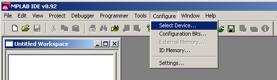
Now we select the processor.
Since PIC10F220 and 10F222 differ only by the amount of available memory, the most practical thing is to create a source suitable for both. The selection of the processor in the control bar of MPLAB guarantee operation of
automatism, managed with #ifdef that selects the appropriate includes.
;--------------------------------------------------------------------
#ifdef __10F220
list p=10F220
, r = DEC
#include "p10f220.inc"
#endif
#ifdef __10F222
list p=10F222
, r = DEC
#include "p10f222.inc"
#endif |
Basically, if you chose the MPLAB project creation or through the menu Configure/Select Device
the PIC10F220 :
the statement #ifdef will let the compiler executes only the highlighted lines:
;--------------------------------------------------------------------
#ifdef __10F220
list p=10F220
, r = DEC
#include "p10f220.inc"
#endif
#ifdef __10F222
list p=10F222
, r = DEC
#include "p10f222.inc"
#endif |
In the case in which it was selected 10F222:
;--------------------------------------------------------------------
#ifdef __10F220
list p=10F220
, r = DEC
#include "p10f220.inc"
#endif
#ifdef __10F222
list p=10F222
, r = DEC
#include "p10f222.inc"
#endif |
Note that the definition of the processor appears in the list of symbols (.lst file resulting from the compilation) preceded by a double underscore
__, that, in the Convention of Microchip, indicates a private label of 'build environment.
In this simple way you can write a single source automatically adaptable to two different processors.
Note that establish the general reference for the numerical values to the root decimal, r = DEC, which is more "natural" than the default
hexadecimal.
Now for the Configuration Word, which is simple, given the limited resources available in the chip.
In particular:
;####################################################################
;
;====================================================================
;=
CONFIGURAZIONE
=
;====================================================================
__config _CP_OFF
& _MCLRE_ON & _IOFSCS_4MHZ & _MCPU_ON & _WDT_OFF |
- _MCPU_ON enable
an internal pull up on MCLR pin, avoiding to add an external component
- _MCLRE_ON enable GP3 as
MCLR
- _IOFSCS_4MHZ enable the
internal clock to 4MHz
- _WDT_OFF and _CP_OFF disabile
Watchdog and code protection
We observe that this chip allows you to:
- have a 4MHz internal clock, which is essential given the very low number of pins: if they were given over 2 to an external oscillator would remain only two more available as I / O. Among
other clock it can be accessible from outside through one of the pin; here this option is not enabled because they serve all the available I / O.
- place an integrated pull-up on the MCLR pin, for which not even need to add an external resistor
pull-up: low count of components in the circuit
We assign now the limit values of the steps relating to the various modes of operation:
;********************************************************************
;*
ASSEGNAZIONI LOCALI
*
;********************************************************************
; Uscita LMCP9701 19.5 mV/°C + 400mV
;
temp Vout ADCdec
ADChex
k1 equ .60 ;
40°C -> 1.180V -> 60 -> 3Ch
k2 equ .70 ;
50°C -> 1.375V -> 70 -> 46h
k3 equ .80 ;
60°C -> 1.570V -> 80 -> 50h
k4 equ .90 ;
70°C -> 1.765V -> 90 -> 5Ah
k5 equ .100 ;
80°C -> 1.960V -> 100 -> 64h |
If We use other sensors (MCP9700, LM35, etc) or other voltage limits and step,
need to change the table.
Now we define the use of GPIO and RAM.
In particular, the control of the LED output refers, as a symbol, directly to the shadow used to avoid the problem RMW.
So the RAM you must reserve a location for this shadow.
Use in a case so simple a shadow of the I / O is not strictly necessary: the load being constituted only by LED, the problem RMW does not occur, but it is still appropriate to use the principle for the correct procedure for access to 'I / O PIC without LAT register.
;====================================================================
;
DEFINIZIONE DI IMPIEGO DEI PORT
;====================================================================
;sGPIO map
; | 3 | 2 | 1 | 0 |
; |-----|-----|-----|-----|
; | in | LEDG| LEDR| AN0 |
;
#define LED_R GP1
;
posizione LEDR in GPIO
#define LED_G GP2 ;
" LEDG " "
#define LEDR sGPIO,LED_R ;
LED R tra pin e Vss
#define LEDG sGPIO,LED_G ;
LED G tra pin e Vss
;#define GPIO,GP0
; AN0
;#define GPIO,GP3
; MCLR |
In RAM they are reserved also two locations for counters required by routine timing.
;####################################################################
;====================================================================
;= MEMORIA RAM =
;====================================================================
; RAM senza banchi
#ifdef __10F222
;Zona di 24 bytes
;----------------
CBLOCK 0x09 ;
area RAM da 0x08 a 0x1F
sGPIO ;
shadow I/O
d1 ;
contatori per Delay
d2
ENDC
#else ;
10F220 - meno RAM
;Zona di 16 bytes
;----------------
CBLOCK 0x10 ;
area RAM da 0x10 a 0x1F
sGPIO ;
shadow I/O
d1 ;
contatori per Delay
d2
ENDC
#endif |
To simplify the use of shadow and avoid the repeat of identical instructions that make heavy reading the list, it may want a small macro to transfer the shadow registers of I / O.
;
local MACRO
; Copy shadow into GPIO
EXEC MACRO
movf
sGPIO, W ;
carica shadow in WREG
movwf GPIO ;
copia nel GPIO
ENDM |
We can add some other macro control of the LED; they are not essential, but are useful to clarify the possible listing:
;
accende led Verde
Verde_on MACRO
bsf
LEDG
ENDM
; accende led Rosso
Rosso_on MACRO
bsf
LEDR
ENDM
; spegne led Verde
Verde_of MACRO
bcf
LEDG
ENDM
; spegne led Rosso
Rosso_of MACRO
bcf
LEDR
ENDM
; toggle led Verde
Verde_tg MACRO
movlw
LED_G ; b'00100' toggle
green
xorwf
sGPIO, f
ENDM
; toggle led Rosso
Rosso_tg MACRO
movlw LED_R ; b'00010'
toggle red
xorwf
sGPIO, f
ENDM |
The flashing is made by changing the status LED or LED concerned. This is achieved with a toggle (reverse state) of the value of the corresponding bit in the register I / O. The toggle is performed with the XOR function; remember that XOR with 1 inverts the value of the bit.
The actual program starts with the classic writing of calibration value of
internal oscillator.
To understand well that for these PIC the reset vector does not point to 00h, but to 'last location of the Flash, where the manufacturer, in testing the chip, writes the calibration value of'oscillator, in the form of an opcode:
movlw valore_calibrazione
So, the first statement that the PIC runs after reset is not what is 00h, but this movlw.
At the next cycle, the wrap around the program counter brings its value to point to 00h, ie all 'area of instructions inserted by' user.
Since WREG is loaded with the appropriate value for the calibration of 'internal oscillator, the easiest thing is to transfer this value to the
OSCCAL register.
The line andlw 0xFE is added
with the purpose of dismantling the possible output Fosc / 4 where this is available (if it is not used, as in this case).
;####################################################################
;====================================================================
;= RESET ENTRY =
;====================================================================
; Sicurezza per il valore di calibrazione
RCCAL ORG 0x1FF
res 1
; Reset Vector
ORG 0x00
; calibrazione oscillatore interno
andlw
0xFE ;
clear bit0: no Fosc out
movwf
OSCCAL |
This action would not be necessary, given that the activities of micro in this application does not require any particular accuracy in the cycle time, but even here it is advisable not to jump instructions that on other occasions may be necessary. Follow a precise procedure is essential not to find themselves with problems whose causes are sometimes identified with difficulty.
The main program starts with the setup of OPTION_REG and the direction of the pin.
To be noted that the Baseline require special instructions OPTION and TRIS, which is obsolete for PIC families superiors.
A semi-graphic helps to understand the function of various bits and assign the right value. Here 's use of the binary number is very clear that not expressing the value in hexadecimal or decimal.
;####################################################################
;====================================================================
;=
MAIN PROGRAM
=
;====================================================================
MAIN:
; inizializzazioni I/O al reset
; OPTION default '11111111'
movlw
b'11010111'
;
1------- GPWU disabilitato
; -1------
GPPU disabilitato
;
--0----- clock interno
; ---1----
done
; ----0---
prescaler al timer
; -----111
1:256
OPTION ;
al registro OPTION
; ADCON0 default '11001100'
movlw
b'01000001' ;
ADC abilitato, GP0 = AN0
;
0------- ANS1
; -1------
ANS0
;
--00---- 0
; ----00--
CH 0
; ------0-
GO/DONE
;
-------1 ADC enabled
movwf
ADCON0
; GPIO
clrf
GPIO ;
preset GPIO latch a 0
clrf
sGPIO ;
e anche la shadow
movlw
b'1001' ;
GP1/2 = out
tris
GPIO |
The evaluation of the results of the AD conversion is carried out with a subtraction from the values specified for the various ranges.
It should be noted that it is necessary to use subwf because
Baseline don'yt have the opcode sublw.
skpc (skip next line on carry
set) it is one of the pseudo instructions supported by MPASM Assembler and that is of more immediate understanding of' equivalent btfss STATUS, C.
Verde_of
;
LED off
Rosso_of
EXEC ; esegue
in GPIO
ml call
ReadAD ;
read ADC
;range evaluation
movlw
k1 ;
< k1?
subwf
ADRES, w
skpc
goto
sel1
n1 movlw
k2 ;
< k2?
subwf
ADRES, w
skpc
goto
sel2
n2 movlw
k3 ;
< k3?
subwf
ADRES, w
skpc
goto
sel3
n3 movlw
k4 ;
< k4?
subwf
ADRES, w
skpc
goto
sel4
n4 goto
sel5 ;
> k4?
; LED driving
sel1:
Verde_on
;
T<40°C verde fisso
Rosso_of
goto
selxec
sel2: ;
40<T<50°C lampeggio verde/giallo
Verde_on
;
verde fisso +
Rosso_tg
;
toggle rosso
goto
selxec
sel3: ;
50<T<60°C giallo fisso
Verde_on ;
verde + rosso
Rosso_on
goto
selxec
sel4: ;
60<T<70°C lampeggio giallo/rosso
Rosso_on
;
rosso fisso +
Verde_tg ;
toggle verde
goto
selxec
sel5: ;
T>70°C rosso fisso
Verde_of
Rosso_on
selxec EXEC ;
drive LED
call
Delay025s ; 250ms
delay
goto
ml ;
loop |
It may be interesting to note that the color of the text, easily accomplished by an editor for programming, allowing an immediate evaluation of the components of each line.
For example, we look at how the 'setting of the color (default typical for listed PIC) stand in the opcodes blue, green commentary and black label and macro.
Let's add a couple of subroutines, one related to AD conversion and 'other generation of the delay wanted.
Simple is always extra management ADC module: no need to capture time between readings AD and later since they are already widely rhythmic routine of late.
The delay is of the usual type waste time, since Baseline does not have interrupt; the structure is derived from the site of
Golovchenko and may be varied at will to obtain a flashing with different frequency.
Of course you can also use the Timer0, which in this application is not any other
function.
END
terminates the compilation.
;********************************************************************
;====================================================================
;=
SUBROUTINES
=
;====================================================================
;********************************************************************
; Read ADC
ReadAD bsf
ADCON0, 1 ;
avvia conversione
lpAD nop
btfsc
ADCON0, 1 ;
wait per fine conversione
goto
lpAD
retlw
0
; Delay = 0.25 seconds
; Clock frequency = 4 MHz
; 0.25 seconds = 250000 cycles
Delay025s: ;249993
cycles
movlw
0x4E
movwf
d1
movlw
0xC4
movwf
d2
Delay025s_0:
decfsz
d1, f
goto
$+2
decfsz
d2, f
goto
Delay025s_0
goto
$+1 ;3
cycles
nop
retlw
0 ;4
cycles (including call)
;
===================================================================
; =
THE END
=
;===================================================================
END |
Note that the return from the subroutine requires retlw, given that there is no return in the instruction set of the Baseline. You might think of introducing a equate:
RETURN = RETLW
to maintain uniformity of writing with other PIC, but this is totally unnecessary:
we can also write directly return, since MPASM performs equally compile without errors, operating automatic replacement with the correct opcode (and pointing out the operation with a
warning).
However, the advice is to use the instruction set of the chip that you are using; This allows you to have a greater awareness of what you are doing in relation to 'hardware.
As for the LEDs, you might think to handle them with two PWM so as to have a passage of the green-yellow-red uniform, but we have seen that in practice the move with the flashing is much more effective for the' operator that immediately identifies with this a time of transition from some situation to
another.
Instead, if desired, a pwm may be applied to the on-state of the LED, adding another timing loop to a frequency greater than 100 Hz, in order to reduce consumption, where necessary, given that the two-color LEDs usually require more than 10mA for have a satisfactory brightness.
Obviously such a structure can also be used to control small relays, opto-isolators or buzzers, creating alarm outputs or care in relation to the measured value. In this case you need to add a hysteresis sufficient to prevent the bounce of the contacts for small changes around the threshold
values.
Hardware.
Given the 'extreme simplicity of the circuit, the construction can be a pleasure or as needed of' application.
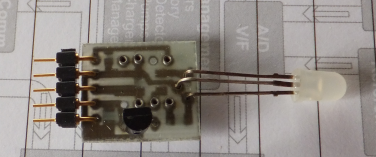
Here a couple of examples of printed circuit boards (scale approximately 2: 1):
Obviously, the SMD circuit
is smaller, but not so much, having to use a single-sided printed circuit.
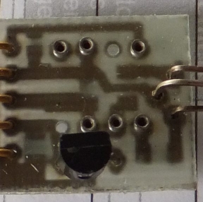 |
However, passive components are used SMD also for the version with the chip in package DIP8 to have a small circuit surface printing. The three-terminal regulator is still in TO92.
In the version in the picture, the base of the chip is replaced with a single pin (not included those relating to the pin is not internally connected to the chip version DIP8).
A pin connector 2.54 allows you to connect the cables with the coupon directly to another PCB.
Given the very low number of components required, the circuit can be achieved in many other ways, even on a
breadboard.
|
Variations.
We see a possible variation: indicate the status of a voltage, for examples that of a 12V battery.
We send all 'analog input voltage to be evaluated through a divider:
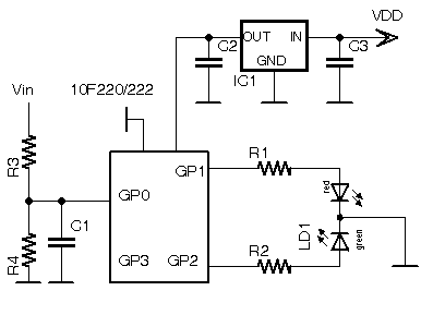 |
R3 and R4 are the divider input. In this case you could have a value of 1: 4, making it possible input voltages up to 20V.
In this way we Vin = 20V -> Vgp0 = 5V.
They may be respectively 6K2 and 2k2 or 11k ohms and 3K9 or other combinations in the ratio 1: 4.
If it is the circuit is connected to the battery of a vehicle, it will be possible to put a zener diode (5V6-1 / 4W) in parallel to C1 to prevent the input voltage reaches a dangerous limit for the microcontroller. If it is not expected that the input voltage exceeds 20V, the zener can be
omitted.
|
Obviously, the divider may be adjusted to the voltage that you want to measure and the same structure adapted to other range of input voltage.
We establish the following conditions of the LED:
| Tensione |
LED |
| Vin
< 10.5V |
Red blinking |
| 10.5
< Vin < 11.5V |
Red |
| 11.5
< Vin < 12V |
Yellow |
| 12
< Vin < 14.5V |
Green |
| 14.5V
< Vin |
Red/Green
blinking |
Here, too, the values are completely adaptable to the ranges that you want to evaluate. Just change accordingly the values of the constants related.
Then we assign the limit values of the various modes of operation of the LED:
;********************************************************************
;*
ASSEGNAZIONI LOCALI
*
;********************************************************************
; Partitore 1:4
;
Vin ADCdec ADChex
k1 equ .134 ;
10.5V -> 134 -> 86h
k2 equ .146 ;
11.5V -> 146 -> 92h
k3 equ .153 ;
12V -> 153 -> 99h
k4 equ .184 ;
14,5 -> 184 -> B8h |
Modifichiamo
l' analisi del risultato della conversione per adeguarla alle nuove
condizioni.
;
LED driving
sel1:
Verde_of
;
Vin < 10.5V Rosso
Rosso_tg ;
rosso lampeggiante
goto
selxec
sel2: ;
10.5 < Vin < 11.5V
Verde_of
;
rosso fisso
Rosso_on
goto
selxec
sel3: ;
11.5 < Vin < 12V
Verde_on ;
giallo fisso
Rosso_on
goto
selxec
sel4: ;
12 < Vin < 14.5V
Rosso_of
;
verde fisso
Verde_on
goto
selxec
sel5: ;
Vin > 14.5 rosso/verde lampeggiante
btfss sGPIO,GP1
; se GP1 e 2 sono uguali, differenziali
goto a1 ;
per usare il ciclo come cadenza per il
btfss sGPIO,GP2 ;
lampeggio
goto
lamp
goto
adj
a1 btfsc
sGPIO, GP2
goto
lamp
adj: ;
GP1=GP2 - differenzia
Rosso_on
Verde_of
lamp:
Verde_tg ;
rosso/verde lampeggiante
Rosso_tg
selxec EXEC ;
drive LED
call
Delay025s ;
250ms delay
goto
ml ;
close loop |
A slight complication is inserted to get the flashing green / red.
The problem that can be generated is as follows: in the absence of interrupts, in order to exploit the cycle as cadence of the flashing with the system of the toggle, it is necessary that the two control bits of the LEDs are different since it is necessary that the first entry in the SEL5 selection have different values for the two bits that control the LED red and green.
If you switch to SEL4 SEL5, or with a growing tension, there is no problem. In SEL4 the two control bits LEDs have different value, so their toggle produces a flashing alternately.
A flow chart makes clear it.
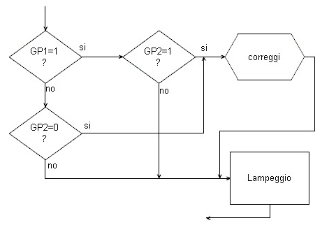 |
If you go directly to SEL3 to SEL5 for a rapid increase in voltage (the acquisition cycle is very "slow"), you come up with the two-bit value of the spread, which would lead to a toggle flashing yellow and not all 'alternating red / green desired.
It is therefore necessary that all 'input of fasesel5 the two bits are of different value. If not, the cycle of the toggle does not allow flashing red / green.
It does not matter how they setup the first time, because the next steps of the cycle will reverse the state and this guarantees the
flashing.
|
Of course you can use other logical paths to generate the flashing, but the one used is the most banal and simple
absolute.
Of course, if you prefer a different reaction of the LED, just change the operations performed at each selection.
Here too we can think about the connection of relays which are inserted / switched off depending on the voltage (always remembering to insert a minimum hysteresis in the switching
points).
A further variation would be to use the GP3 as digital input and select with the voltage value applied two different configurations of the set of intervention and / or LED's function, thus being able to use a spread chips for two different
applications.
As we see, a very simple programming in Assembly on a PIC among the smallest available (not only in size, but also as resources) allows sensitive
results.
The program will serve as a basis to create all kinds of indicators. You can associate different conditions of the LEDs and different thresholds, with different outputs from the two-color LED
used.
Documentation.
|