Battery power supply 2-5V
|
A battery power supply for projects in microcontroller (and not only).
A power supply...
If you are experiencing circuits, need a good power supply.
Certainly there are few electronic voice that give rise to a choice as wide as that of power. Why, then, add another?
Mainly because we needed an independent power supply for our demo board and for development in
general.
Of course, you could use one of the many wall plug made in
China, but the request was to NOT have a connection to the power grid, for several
reasons: first, to keep isolated the circuit under test and avoid possible power loop during
development; secondly, for not having more wires and contraptions on the table already
footprint.
Therefore, a battery power.
The problem of the batteries is that they have such values as to combine almost for nothing with the typical voltages of the logic
circuits, which are essentially 5V and 3.3V. Certainly the recent microcontroller can operate between 2 and 5.5V, and two or three NiMH or Alkaline batteries or a lithium cell would
fit.
But it is likely that, during development, you want to use a specific voltage sufficiently precise and the batteries have a voltage whose value falls in the
'use. So there must be some stabilizer, with the possibility to switch the 'output between the values
most commonly used.
A first idea is to use a higher voltage, such as 4 1.5V or 7.5V Lithium and lower with a LDO. There are, however, some contraindications:
- Alkaline batteries are expensive and if they are empty they throw
- The rechargeable batteries have a lower voltage (typ. 1.2V) for which the 5V would be possible starting from at least 5 elements. Too cumbersome.
- Lithium batteries in small packages from 7.5V you can recover with relative ease, but the power lost on the voltage drop of the linear regulator would lower the
yield.
This brought the solution switch mode. And, in this case, it is possible so that a step up one step down.
The application does not require a high current: 300 mA should be enough to power the vast majority of circuits around the microcontroller, even using small LCD with backlight or some 7-segment display. It is opted for a
step-up, given that the controller for the most recent these circuits have high yields and function as
"battery squeezer", even with very low voltages (below volts).
To get an object as small as possible, the choice is essentially the battery or accumulator
cylinder, then a voltage from 1.2 to 4.6 V. It should be a step up.
There is however, a degree of autonomy. So a yield as high as possible by the
switching, and a capacity of the batteries is not minimal. Are excluded a priori as the AAAA for now uncommon and suitable only for low power
devices. The AAA-size batteries have smaller size of AA, but also a reduced
capacity. In addition, the AA is the most readily available, either as elements carbon and
alkaline, non-rechargeable, and as NiMh or NiCd or other technologies, thus becoming the best
choice.
As regards the number, only one battery does not create problems with a step-up that is required to increase at 3V, but is less suitable for 5V, especially if we want to extract a certain
current. Three elements are possible, but the end result becomes more
cumbersome. Two elements are a good compromise.
The IC offering suitable for the purpose is very broad, because the' battery power has become commonplace
|
|
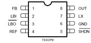
Among all the possibilities was chosen the 'integrated L6920
of ST (similar is the Maxim's MAX1674), which has many points in favor:
- part with a very low voltage (1V), so it may "squeeze" on the bottom of the batteries
- can be set to fixed output voltages 3.3V and 5V without dividers
- it is possible to have a variable adjustment between 2 and 5.2V
- The chip also contains the comparator to check the battery status
- it's resistant reversal of the supply voltage (battery inversely
inserted)
- requires a minimum number of external components
has a high yield (> 90% at 200 mA).
|
 |
Compared to more recent and less expensive MCP1640
from Microchip, L6920 allows a higher current, but, above all, it integrates the comparator to control the battery, which is absolutely essential if you intend to use rechargeable batteries:
if non-rechargeable batteries is useful to proceed to complete exhaustion of
element, it is unimaginable to use rechargeable batteries without a system status indication, as a
discharge too deep dramatically decreases their life expectancy. MCP1640 goes well, thanks to its tiny size, for finite systems, where the microcontroller can verify through ADC input or module HLVD battery status, while here it is a module designed to be used in all applications, the full range of functions is essential. The greater cost of L6920 largely compensates for the implementation of a comparator exterior, with its reference voltage and expense
necessary.
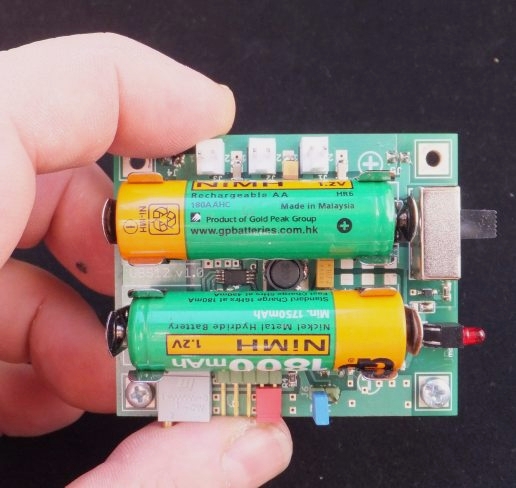
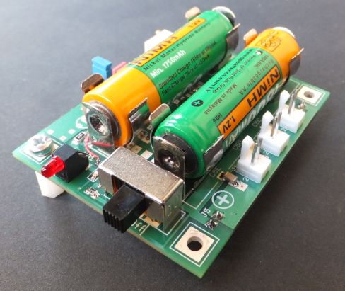
UBS-12 module.
The result is the form UBS-12 with the following features:
- small size (54 x 68 x 22 mm approx), compact (pack of cigarettes)
- programmable output voltage fixed 3.3V and 5V
- variable stabilized output voltages from 2V to 5.2V approximately
- current capacity: about 400 mA at 5V
- higher yield of '80%
- powered by two AA batteries of any chemistry (NiMH, NiCd, alkaline, carbon, Ag, Li)
battery indicator
- battery indicator inversely inserted
- possibility of direct connection on breadboard
- directly compatible with Uniboard
- suitable for all kinds of food development system
It looks like this:
The design.
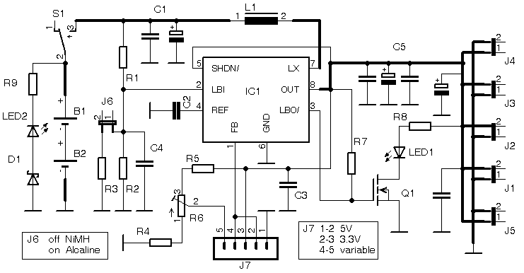
This is the electrical circuit:
E questa è la disposizione dei componenti.
 |
The printed circuit board is a double-sided metallized holes, fiber glass, silk screen with solder and
components.
With the exception of the media of batteries, jumper and a few other parts, the majority of the components are surface
mount.
In the diagram, the capacitors C5 and C1 represent the groups of more elements with low ESR in parallel, in order to obtain an even lower ESR, together with a current capacity of high peak.
This is intended to minimize the ripple and optimize performance.
The configuration jumpers, those of the load connection, switch and LED, together with the trimmer multiturn adjustment of variable voltage, are easily and comfortably
accessible.
Also the batteries, mounted on elastic holder, are replaceable with extreme
ease. |
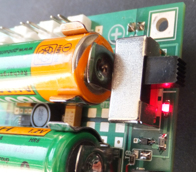
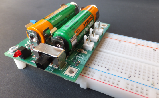
Two AA batteries (B1 e B2) are the main power source; S1 switch connect the
batteries to the rest of the circuit. Screen printing is indicated on the correct polarity of insertion, but, in any case, is implemented a security system
anti-distraction.
 |
In the OFF position will still function the branch consisting of D1, R9 and LED2. Its purpose is to provide a visual indication when the batteries have been inserted on the contrary, the diode D1 normally does not lead, so if the batteries are inserted correctly, the LED current sink. If you mistakenly reverses the polarity of the batteries, the LED lights up.
It is located under the 'switch and lit, it indicates not to operate it.
If you are replacing the batteries with the 'switch is ON, L6920 is designed to support the' reversing 'power and the LED promptly notify the abnormal
situation. |
This solution, seemingly simplistic, was chosen because it is the 'only one that does not introduce any voltage drop between the battery and the DC / DC converter, something that you would have with a diode in series (not less than 0.4V using a Schottky ). Better would be a MOSFET P, which however would introduce a resistance and that, in any case, would require a visual indication of the fact that the batteries have been inserted incorrectly.
The LED, however, combined with the resistance of 'L6920 to' reverse polarity, is simple and
effective.
Could be omitted? With regard to the integrated, yes, but it should be noted that there are also electrolytic capacitors and these polarized voltage to the contrary, are at risk if the situation persists that
much.
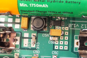 |
The step-up converter uses the 'energy stored in L1, which is an inductance screen low
resistance.
The MOSFET switch is internal to 'L6920 and can take over 1A.
All 'output, pin 8, other low ESR capacitors to reduce ripple to negligible values
for the power of a microcontroller.
The printed circuit, with a large ground plane, is designed to have the least possible
impedances. |
Particular attention has been paid to the choice of 'inductor, which are larger than those used in other applications of this step-up converter, the choice is due to two factors:
- The current
- The resistance of the coil
In particular, the data sheet of L6920D specifies that the current of the switch has a maximum of 1.2A and then, in order to obtain maximum performance, it is necessary that the 'inductor can sustain this current. Furthermore, its resistance value is very low, so as to improve the yield. The fairly high value of 'inductance maximizes the current and minimize the
ripple.
Similar care has been taken in the choice of capacitors, which are very low ESR electrolytic tantalum with (15 Mohm), coupled with multilayer ceramic for further improvement of the performance.
In this way we obtain a low ripple with a high output current.
A special feature of the embodiment is the thermal coupling of the integrated with the copper of the printed circuit, performed with a layer of thermo-conductive compound to 'silver applied below the package; this allows to improve the temperature of the component in' use to prolonged high
current.
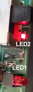
L6920 has an input LBI (Low Battery Input) that is connected to the battery voltage through a voltage divider (R1, R2 and R3), which establishes a level of intervention of battery to 2.0V (jumper J6 closed) for accumulators NiMh and NiCd and 1.8V (J6 open) for alkaline and carbon. The internal comparator activates the 'LBO output (Low Battery Output) is normally at level 1. This output drives Q1: The LED1 will be lit until the battery level is greater than that set on pin LBI and will turn off when the batteries have lower
voltage.
Observe that the drive will continue to operate even though the 'low battery indication is active. This is wanted because it makes no sense "to cut" suddenly the 'power circuit connected: the' user is warned of turning off the LED1 that the situation of the batteries is the limit and the case to replace them. In this way has the whole 'as comfortable as possible to end what is going on, then replace the batteries.
LED1 and LED2
LED1 with LED2 serves several functions simultaneously:
 |
S1 |
LD2 |
LD1 |
Funzione |
| OFF |
OFF |
OFF |
power supply off |
| x |
ON |
OFF |
batteries reversed ** |
| ON |
OFF |
ON |
power on and status ok |
| ON |
OFF |
OFF |
batteries down or short circuit at output |
As LED1 is powered by the drive, acts as a no load to stabilize the output; its brightness will be the maximum and minimum voltage 5V to that of 2V.
WARNING **:
- ST declare a full strength despite the reversal of the supply voltage for L6920, we highly recommend turning off the power to replace the
batteries. The 'switch in the OFF position can be observed clearly LED2, immediately detect a wrong insertion and correct the situation without applying reverse voltage to the
circuit, which might be harmful to other components, such as electrolytic
capacitors.
Batteries status selector - J6
The threshold for low battery indication depends on J6:
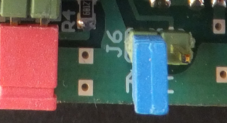 |
| J6 |
Soglia |
Batterie |
| inserted |
2.0V |
NiMh & NiCd |
| not inserted |
1.8V |
alcaline & carbone |
|
Turning off the LED LD1 warns of low battery situation. Note that it is only a visual indication and that the drive is locked, the 'user at his discretion, if necessary, will not be obliged to suspend work (since the chip continues to operate under the volts) and may replace the batteries at a later time.
Note that, in the case of non-rechargeable batteries, it is possible to proceed again to below 1.8V (0.9V per element), until the download more absolute (the converter operates with voltages below the volts), but it should be borne in mind that the internal resistance of the batteries becomes prominent and their ability to provide a current below the 0.9-0.95V per element is reduced drastically. For rechargeable batteries, shutting down the LED1, it is advisable to replace and
recharge.
Output voltage - J7.
The output voltage is determined on two fixed values or variable with the jumpers J7
| 5V |
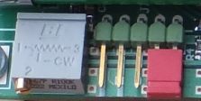 |
| J1 |
Tensione |
Note |
| 1-2 |
5V |
factory fixed voltage |
| 2-3 |
3.3V |
factory fixed voltage |
| 4-5 |
2 < V < 5.2 |
variable voltage |
In the jumper position 4-5, the output voltage can be adjusted finely with multiturn R6.
WARNING:
-
It's necessary to insert a jumper in the pinheads voltage selection
-
ONE jumper must be inserted at a time
-
maneuvers switching off and on the jumpers are made
strictly with the module off
|
| 3.3V |
 |
| var. |
 |
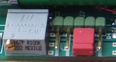
Outputs - J1-J5
Output is available on 5 different connectors:
J1, J2 and J3 have a Molex connector 2.54 male polarized plugs for flying connections with female Molex
cable.
 |
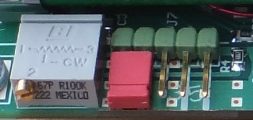
J4 and J5 are provided for connecting the module to a breadboard, using the plugs step 2.54.
With these plugs, the unit fits perfectly in the ways of power board. |
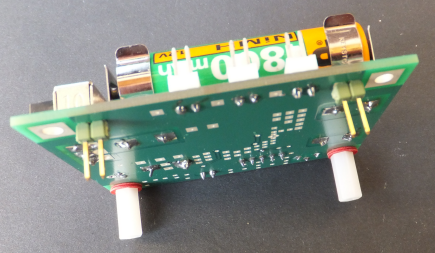
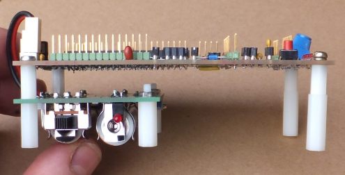
To take full advantage of the space of the breadboard, UBS-12 is supported by two nylon feet that lead to the same level of breadboard without putting any pressure on edge of interconnection.
 |
The direct insertion of the power supply module is possible for all standard breadboard with two-way power per side, with the positive to the negative rail red and the blue.
Mounting only J4 or J5, you can connect to any type of card
prototype.
Power switch, LED indicators and configuration jumpers are easily accessible without removing the 'power from the
breadboard.
|
Having provides the main supply voltage logic circuits, 5V and 3.3V, UBS-12 allows you to create many different circuits on the breadboard, even with the 'use of our card Miniboard.
Furthermore, the possibility to have stabilized voltages in a wide range, between 2 and about 5.2V, allows to experience the widest range of circuits.
UBS-12 + Uniboard
UBS-12 must be conneted to the Uniboard
with a short biploar cable with a Molex plug (J3); all outputs are available for direct connection to other
circuits.
 |
The "package" consists of the Uniboard
and from 'supply is a solid and stable, it does not take up unnecessary space on the bench, does not require cables for connection to external power and has no connection to the power grid.
Simply connect the development tools (Pickit, RealIce, etc..) And you can begin to work safely, to carry out development without problems of interference and noise, without the clutter of cables and in a very limited space next to the
keyboard. |
The possibility of obtaining stabilized voltages between 2 and approximately 5.2V allows to test all kinds of application and verify the response of the microcontroller and of the components in the most diverse situations of power.
Other applications.
UBS-12 was designed not only as power supply of Uniboard
or breadboard, but also to be easily integrated on any kind of prototype cards
or realizations of all types where handmaid a voltage independent of between 2 and 5V.
Another practical use is to 5V portable generator for charging cell phones, MP3 players, photo rooms and other parts that are usually charged from the USB port. The ability to use all kinds of batteries eliminates the problems of recovering a particular type of accumulator in situations or places where this is problematic.
A simple cable fit the 'output UBS-12 with the USB plug required.
For those who do not have the time or way to achieve if the 'power, UBS-12 is available as a finished product or as a kit with SMD components pre-assembled, or just the printed circuit board.
|