|
A "different" PIC
programmer
|
that is, there is no need to buy or build programmers for PIC ....
"Still the nth programmer!?"
But no. Because it's not!
Connection with the ICSP/ICD
can program the PIC on-circuit and external programming device just do not
need.
Or rather, it can sometimes be convenient to have a programmer, for example, when we plan a handful of processors equal or is not comfortable doing on-board.
Then we have to build or buy one of the many and reviled
programmers?
The answer is still no, because we can program using ICSP PIC without any special hardware. Simply use one of the
Microchip
(PICkit, ICD, Real ICE) that also function as programmers.
ICSP
The first point concerns the programmer seems to be the 'hardware.
We know that a programmer for PIC is interfaced to the PC where the program resides management in three
ways:
- serial port using RS-232
- parallel port connection
- USB connection
In any case, whatever the 'interface used,
- the connection to the PC is converted into a link clock + data at TTL level
and connected to the PIC as ISCP
- management program requires a special software that runs on your PC
|
A "programmer" is not worthy of its name if it has at least one ZIF (Zero Force Inserction socket), which, of course, if used frequently, it has nothing to do with the usual sockets integrated.
but are also used ordinary sockets, especially if you want to save the most and if you seldom use the device. Even here, just do a short ride on the WEB to find thousands of different
realizations.
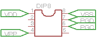
But it should now be clear that, for any PIC, from 6 to 100-pin:
|
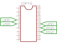
only the pin PGD, PGC and Vpp (together with power supplies) will be those used for
programming.
Others do not participate at all to step! :
|
In essence, therefore, the real hardware to program the PIC is simply limited to the ability to access pin PGD, PGC and Vpp and supplies. You do not need nothin
else.:
The Software
And 'no doubt that we need a program for the control of the programmer in order to transfer the object file from the PC to the PIC.
And this part usually appears to be secondary to 'hardware. But it is not.
In the words of a Tale, "without the software, the 'hardware is just a pile of components without life."
And the programmer software must be able to manage the various devices, which are constantly evolving with the 'release of new models every short time.
This program is a key part of the planning system: as in all the realizations which are contained microprocessors, the 'hardware without software control is dead matter.
It is therefore necessary that this software to do exactly that which is expected, and at best, in addition to being updated, following in real time the continuous evolution of the products.
It must be said that there are initiatives open sources, such as IC-PROG
or WINPIC800
that can provide security of continuity, even if their management is left to the voluntary sector. And sometimes a community on the Web can work with determination and seriousness greater than those of a company.
To be or not to be....
The problem, however, place to 'start is this: but do we really need a
programmer? That is, we must therefore build one of the many patterns or kits
available?
From what we have seen so far we can draw some conclusions:
- a "programmer" is essentially made up of something that I connect to the PC
- this "something" has a support for holding the PIC ,or alternatively,
more PIC (gang programmer)
- this thing does is transform the signals from the PC to the levels necessary to
PGD, PGC and Vpp and apply them to the PIC as specified by ICSP
- this "something" requires a management software
|
Of course I can successfully replicate one of the many schemes on USB (as serial and parallel connections are problematic). Or can I buy one of the many
kits.
But this something exists already and is just one of many tools Microchip, from
Pickit.
Parts 1, 3, 4 I have already available at a cost that may be lower than that of the realization home made. Just add us part 2 and you're
done.
Parenthesis: why take away the taste of do-it-yourselfi?
You are not removing this taste, but simply making an observation:
If you need to dig a plot, buy a good hoe or a spade cars built there usually bronze
age?
That is: the controller is an optional accessory to be reliable is not seen with the eyes or is measured by the meter if the program is loaded correctly. You can not see if the programmer has abused the chip with voltages and timings inadequate. Not even a hobbyist would think of build themselves a hoe, it is from the Neolithic that this does not happen. And if the difference in cost between the hoe Neolithic and the business is in favor of latter 'falls any
discussion.
A self-construction is always possible, but it will be a source of teaching only when you will be able to understand exactly what you are doing. Otherwise it's just a run more or less a pattern of others. And when problems occur it would not be able to intervene.
Furthermore, the difference in cost between a PICkit and another object is commercial, not infrequently, in favor of the PICkit, and even the do-it-yourself, perhaps one of the clones, doing the math, it costs much less .
And, less than a skill not common enough, the final product is much less handy and utilitarian 'original.
Closed parenthesis.
So:
- given that Microchip has made access to the pins PGC, PGD and Vpp a "standard" well-documented
it is possible to realize a socket suitable for each chip. But, if desired, also a socket suitable for most chip.
And add to this a more or less complex electronics, cars constructed according to one of the many schemes?
Since there is already this mail in Pickit, which are just access ICSP.
why not combine the two?
Good ideas as the project GTP-USB assume self build everything, but do not realize that any electronics to be built to interface the PIC to the PC it is just, always a connection ICSP. To invest time, resources and talent to redo what is already there may not always be the 'best idea.
Also because the Pickit not only serve as ICSP, but also as ICD, which is not a normal programmer.
And how do you work on embedded without a debugger?
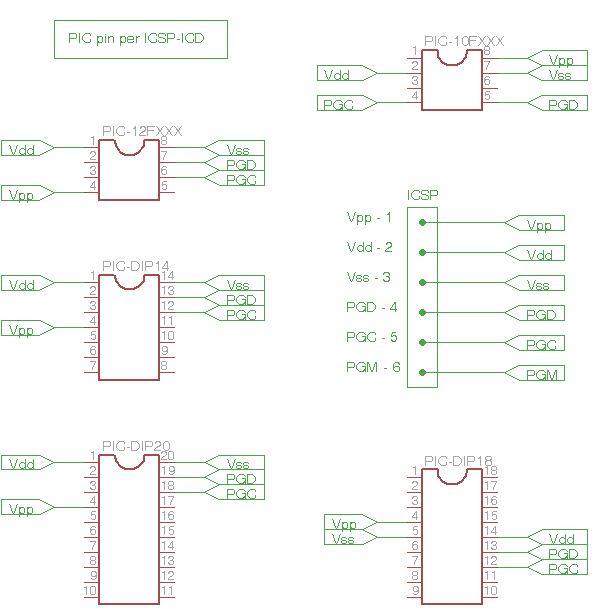
Some schematics
If we look at the 'pin assignments for the' access ICSP / ICD, we note that Microchip has operated in such a way as to achieve a certain compatibility, and of course, the same physical location of the pins in different
packages.
This allows us to make the socket to insert any chip in a DIP package and make sure that the connections are correct ICSP.
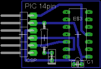
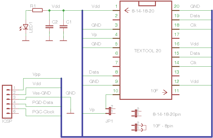
Here then are some diagrams to connect the various PIC to 'Pickit of ICSP.
All adapters has been added, compared to pure ICSP connection, an LED with its limiting resistor, between Vdd and Vss to view the situation. The advice is to use LED with low current (<1 mA), but if it is not considered useful can be omitted, together with the resistance.
A capacitor 0.1uF, always between Vdd and Vss cancels any problems on 'power (this, however, is better to leave ...).
The hooves are better with tulip contacts if you think to use them intensely.
And is simple crearsene other for each type of package.
All roads lead to Rome.
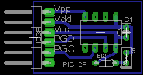
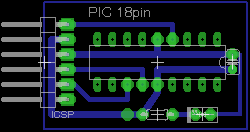
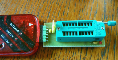
But we can gather in a single module the various solutions: the position of the pin access is such that only one socket is capable of supporting chip 8/14/18 and 20 pin.
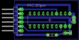
Here, then, a "general purpose" to the PIC pin 8-14-18-20 and on which there are also the
10F 8-pin, with its inevitable ZIF: a little bit expensive, but it makes the job a lot
easier.
All chips have a 8/14/18/20 pin pin 1 aligned to the lever of Ziph. The jumper is open.
The PIC10F in DIP 8 have pin 1 aligned with the 'opposite end of the socket and the jumper is
closed.
All circuits are supplied directly from the Pickit and plug directly into the connector.
Remember to select in the setup menu (Programmer-> Settings-> Power of the main menu of MPLAB) 's board power from the
Pickit.
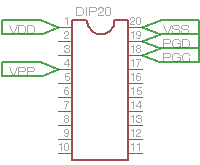
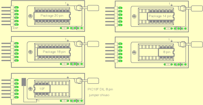
Here's how to insert the chip into the socket according to their package
The 8-pin chip to 20/18/14 and have pin 1 aligned with pin 1 of the socket. The jumper on the printed circuit is open.
8-pin PIC10F chips are aligned on 'opposite extreme and the jumper must be
closed.
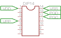
Do it !
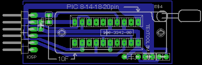
All circuits are proposed single-sided and easily achievable at home.
Not wanting to make a cs (which, however, is the preferred option), you can simply use the point-to-point on a
breadboard.
LED and resistor are optional (use LED 1 mA or less).
The capacitor, 0.1uF, they function to stabilize the 'power.
The jumper is used to select the Vpp in the case of PIC10F
| Package pin |
jumper |
| 8-14-18-20 |
open |
| PIC10F 8 pin |
closed |
If you do not plan to use the 10F 8-pin, you can delete the jumper.
The 6-pin connector, 2.54 (1/10 ") is of gold and bent 90 ° to engage directly in the PICkit without an
adapter.
How it work.
Nothing could be simpler: just plug the stick in the development tools.
We are talking about the PICkit mainly for two reasons:
- may act as programmers from both 'development environment MPLAB IDE, either as stand alone through a management program made
available from Microchip
- can directly power the chip during programming, as pick up power from the USB connection
They can also work as a programmer-to-go, which is separate from the PC, after loading this firmware to download.
These features I make them ideal for this application, although you can also use other tools.
The program 's use of the PICkit programmers as a free download from the Microchip areas dedicated to
the product.
These applications are fairly straightforward and easy to use. In any case, for those who need a tutorial about it in
Italian,
here.
Other information about PICkit:
About PICkit2:
and PICkit3:
|