|
Clock circuits.
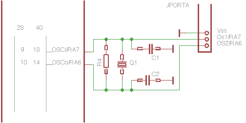
If the PIC 18 and various PIC16 can operate with the internal clock, on Uniboard is expected, however, the possibility of
adding:
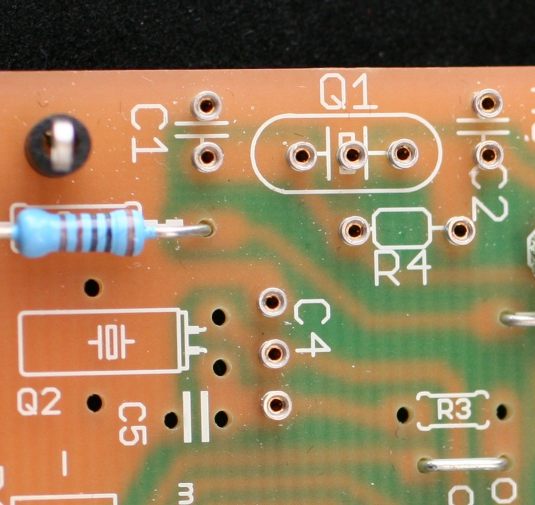
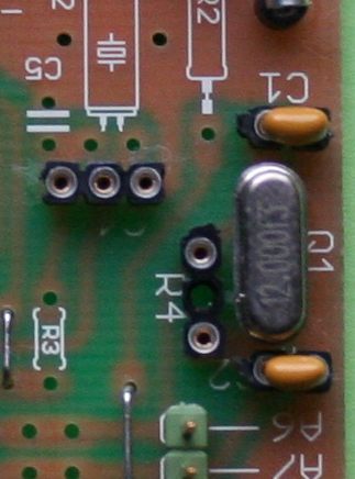
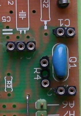
- the classic quartz oscillator: Q1 in HC49, with the capacitors (C1, C1 and the resistor
R4)
- or a three-pin ceramic resonator in place of the crystal
- or RC
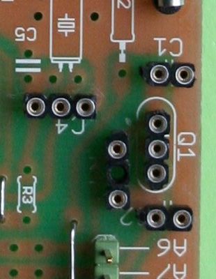
Using pin removable components can be changed, inserted or extracted at will. But it is also possible to solder directly.
In particular, for the crystal are used three pins, which allows to insert also resonators with integrated
capacitors.
Here are the changes:
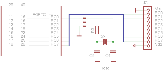
In this way it is possible to test all the possible options, given that, even if not perfectly ideal, the pins of 'oscillator are reported to the external connector to plugs, in order to exploit both external oscillators, is the extra functions of these pins, programmable as GPIO output or clock / 4 (with internal oscillator modes INTIO1, INTIO2).
Even here, the use of removable pin allows a rapid variation of the components or their complete elimination, depending on the mode of oscillator that you will use
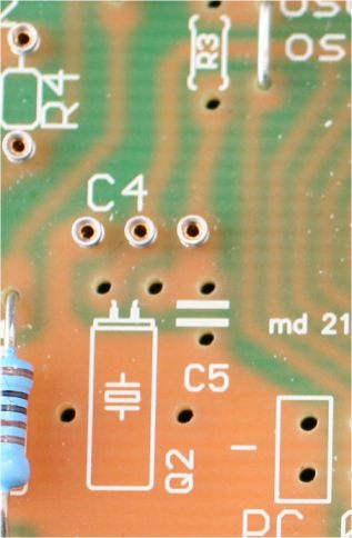
Timer1 oscillator.
On the pcb you can install directly the components relating to 'the Timer1
oscillator.
Also here the parts can be welded or installed on pin, but, in particular, has been provided for a three-pole connector to directly enter a sub-module that carries all the components necessary to
the oscillator.
 |
This allows you to enter the components if required, leaving it completely free of any load pins RC0 and RC1.
In this case, the space of R3 on the printed circuit will be replaced with a bridge.
Recall that the R3 has the purpose of reducing the current in the crystal at low excitation power, to maintain the proper load characteristics provided by the manufacturer of the crystal. Its value, of the 'order of 200-330 k, depends on the quartz used.
On the sub module is already installed on the correct strength for quartz used.
|
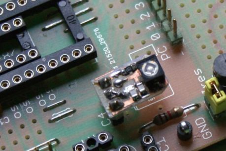
In the sub module in photography can be seen even a variable capacitor with the purpose of perfectly center the oscillation frequency desired, which usually is
32768 kHz and has the aim to implement real time applications.
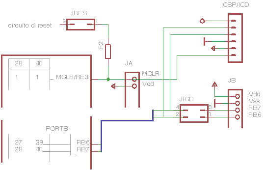
ICSP/ICD:
Obviously, PIC development need ICSP/ICD connection.
 |
The J1 connector is expected to engage directly in a Pickit, but you can make a cable adapter for any other tool, such as those that come with an RJ (ICD and REAL ICE), or buy from Microchip appropriate adapters
ready.
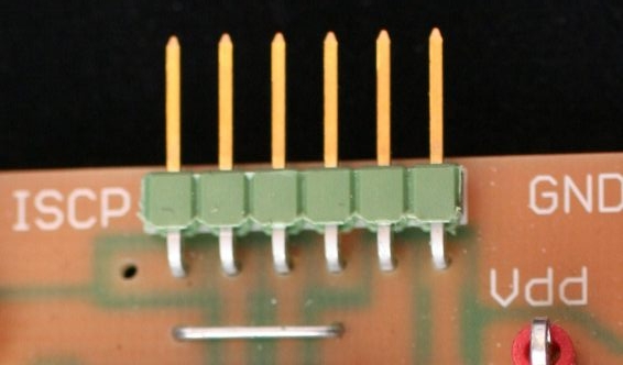
An additional test points can be welded to pick up the signal PGM / spare the PICkit (in the picture you can see the well bore engagement of any
plugs).
|
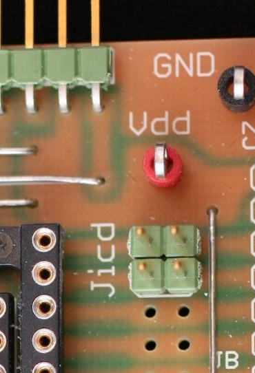
Note that a pair of jumper (JICD schema) allows to separate pins on the serial communication programming or debugging (RB7, RB6) by the plug connector of the 'I / O.
This allows to maintain a load applied physically to the connectors of I / O and does not detach during debugging or programming, by simply separating the circuits with JICD, and then reconnect them at any time.
In addition to these, there are two test point jumper ring to attach any equipment such as oscilloscope, multimeter, logic state indicator,
etc..
The test point with red ring is connected to Vdd.
The test point with black ring is connected to ground. Other test points of mass are distributed in other areas of the circuit.
|