Linear Power Supply 0-10V
0-1A
|
A "state of the art" linear power supply.
Small linear power supply laboratory using integrated (almost) last
generazione.
A laboratory power supply must have variable voltage and current.
For small applications around microcontroller or linear often serves only a voltage below 10V, possibly varying from 0, but precise, stable and free of ripple, with currents that generally do not exceed the
ampere.
The solution that we think in the first instance is that of a linear regulator with three pins, typically LM317. The problem of this component is twofold:
- in the first place, it does not allow the adjustment of the currently secondly, has a minimum voltage over the volt. To solve the first external components needed.
- for the second, should be a negative reference voltage.
In both cases it complicates a simple circuit and eventually be worth implement it differently.
Linear Technology
has created a linear regulator monolithic "three-pronged" called LT3080.
Despite being on the market for some time, there is little mentioned among hobbyists (apart, often with little expertise, in the 'context of' high fidelity audio, for the low output noise.), In favor of other
3 terminals more "ancient". The causes, in addition to natural inertia (and to always condemned lack of information), are certainly to bind to the (until recently) not immediate availability in Italy and cost, which, as often for the products of Linear, it is quite high (about twice LM317).
Despite this, it is worth to take them into account, as they have more opportunities than their
predecessors.

For Your info, Linear have on catalog a family based LT3080.
- LT3080-1, parallelable without serie resitor
- LT3082, output 200mA
- LT3083, output 3A
- LT3085, output 500mA
- LT3081, output 1,5A, parallelable and with current and
temperature monitor
|
LT3080
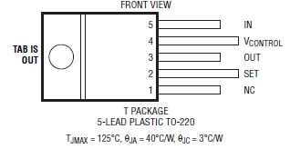
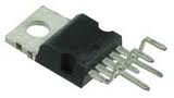
In fact, LT3080 has 5 terminals and is made in many variations SMD and, fortunately, also in a TO220-5, which is what we use
here.
The pin's functions are:
- IN - regulator input
- OUT - regulator output
- SET - adjust input
- Vcontrol - optional separed power for internal logic
The pin 1 is not connected internally and can be left free or connected with any other; the tab, however, as common in this kind of components, is internally connected with the terminal OUT.
This determines if more LT3080 are lying on the heat sink, you must isolate
them.
Even with the terminals 5, 4 of which are active, it is classified in the family of linear three-terminal. Its peculiarity, however, differentiate it from other previous
models:
- is fully floating respect to ground and can therefore operate both as a voltage regulator
or current regulator
- is a low-dropout: the difference between the input voltage and the output is reduced to just 350mV. This allows embodiments of stabilizers where the difference between the input voltage and the output is minimal, as will be the minimum power lost in
heat.
- It contains a source of current reference and is programmable with a single resistor
Output can go to zero without the need for negative voltages
- These currents up to 1.1A and input voltages up to 36V (LT3083 comes in 3A and 23V)
- It generates noise less than 50uV
- It has a better load regulation of 1mV and 0.001% with respect to the line
- It is stable even with small value caps
- It is placed in parallel to increase the output current by adding in series a ballast resistance of small value
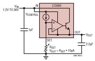
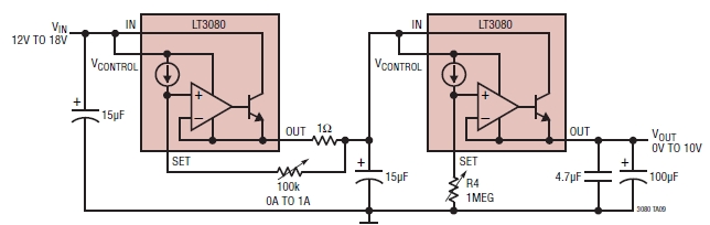
The typical application is this:
These are respectively:
- LDO with a voltage drop less than 0.4V, the input between 1.2 and 36V and adjustable output stabilized
We observe that it is necessary only one resistance than the two used by other three-terminal regulators, with the output voltage directly proportional and linear with respect to the value of the resistance
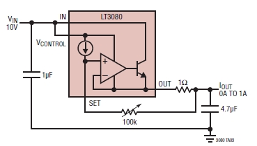
- a generator of constant current from 0 to 1A. In the classical way, the current control is carried out on an external resistance in series to 'output. Here it is how you do LT3080 is fully floating with respect to ground and constitutes virtually a current limiter 2
terminals.
The spreadsheet data, then, suggest an interesting application, by connecting in series the two configurations to obtain a simple, but effective variable power supply with current
regulation:
We just have to try.
LT3080-1 is quite similar to the LT3080, but integrates a resistance of 25 milliohms in series to 'output. This allows the parallel without external components, to increase the current supplied. And 'only available in MSOP and DFN.
The problem with these packages is that they are or planned to use the printed circuit board, multilayer mainly, as a heat sink through a metallic pad (exposed PPAD) on the underside and that is very difficult to treat without professional equipment mounting.
However having the need, even LT3080 is parallel clustering, but you need to add resistance
externally.
|
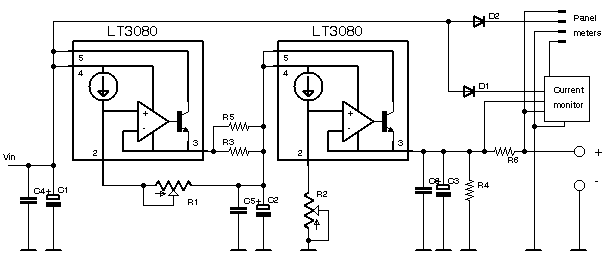
The circuit.
Being integrated components specifically designed for these applications, the circuit is simple and follows the extra
application recommended:
The first LT3080 limits the current to the second LT; This adjustment is made with the potentiometer R1 100k deriving a voltage proportional to the current from the series resistor 1ohm (= 1V per ampere).
The second regulator is that relating to the voltage, which is varied with the potentiometer R2 1M, powered by the internal source of current from 10uA (10uA * 1Mohm = 10V).
C1, C2, C3 are electrolytic capacitors (aluminum, low ESR), while C4, C5, C6 are ceramic mutistrato X5R, for the stabilization of the circuit. Compared to 'application values are greater, to avoid surprises.
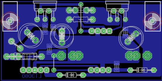
And here is its molded equally simple
The two LT are positioned on the board to connect them to a cooling fin.
Precautions.
Some important points to be considered:
- the component is expected to respond rapidly to variations in line and load and this requires a "bandwidth" high. The result is of course that the pin SET is quite sensitive
- given its "reactivity", it does not require large capacity to compensate for inadequacies of the integrated functions, but it must be ability of quality, in the sense that must be selected as if it were a switch mode.
That is, no electrolyte whatsoever, but low ESR elements and, in particular, multilayer ceramic for smaller
capacities.
- always similarly to SMPS, also this circuit requires a minimum load for stability. That does not work in
vacuum.
- although LDO, it is always a linear, that will transform into heat the power equal to the product between the input-output difference voltage and the current. Put simply, heated and needs a heatsink
These are the main points, of which two should not be underestimated. In the prototype it has been used a mix of low ESR electrolytic and ceramic X5.
For those who recovered, the low ESR can be easily removed from mainboard or similar products; it is of the electrolytic which are used in VRM onboard and that, therefore, are ideal for this application. It 'should, however, that it is not very old cards or who have worked for too many hours: in this case the electrolyte, they have a "maturity", may be to
throw.
Components.
| LT3080 |
2 pz |
TO-220-5 |
| 1N4148 |
2 pz |
|
| C1 |
1000uF - 25V |
low ESR |
| C2 |
47uF - 25V |
low ESR |
| C3 |
470uF - 16V |
low ESR |
| C4/5 |
100nF - 50V |
multilayer X5R SMD1206 |
| C6 |
4.7uF - 16V |
multilayer X5R SMD 1206 |
| R1 |
100k lin. 10% |
cermet or plastic |
| R2 |
1M lin. 10% |
cermet or plastic |
| R3 |
1ohm 5W |
adj. with R5 |
| R4 |
1k 2W |
|
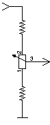
The potentiometrs.
The problem of the potentiometers is not secondary.
As seen above, current and voltage are linear functions of the current flowing in the variable resistance connected to pin September So, first of all, they have to discard all non-linear potentiometers.
It should be also considered that the potentiometers are not precision components; Normal is a tolerance of 20%, and this will be reflected in the value obtained by the adjustment at the stroke end. So if the potentiometer sets the voltage is 900K instead of 1M, it will get out only 9V
maximum.
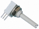 |
It is resolved using potentiometers good quality, with the track in conductive plastic or cermet.
Those used are models with tolerance to 10%, but that in fact have proved to be much more precise.
Certainly the 10 laps would be the 'ideal, alme3no for adjusting the tension, but in practice those at 1 revolution of good quality were adequate, without spending capital for
multiturn.
|
They should be excluded absolutely elements recovered from surplus, used, rusty, etc., as if the track is not of good quality, it will be difficult to center the voltage / current desired. It must also be considered that,
where the contact between the brush and the track is fallacious, its interruption leads the output voltage to the value of that of the input, with the results imaginable for a sensitive
load.
The Rs.
The resistance R3 from 1ohm determines the voltage drop of 1V @ 1A of current. This voltage is tapped with the potentiometer 100k and determines the current limitation.
Here the precision of the potentiometer is in relation to that of the resistance; differences from the nominal values will be reflected in differences in scope.
In the prototype, not having a resistance of 1ohm precision, they have been used a 5W to block, that, between the terminals and the slopes, was abundant and was corrected by paralleling an 'other (R5, in this case from 6.8ohm), obtaining a full scale by little more than 1A.
Minimum load.
Given that it is a floating controller, to obtain the "adjustment" should be a minimum load, otherwise it can not act l 'stabilizing action; The data sheet indicates 0.5mA.
In practice, the R4 1k - 2W is a proper load.
Operate the 'no load power supply brings the output voltage to be unstable and random.
Recall that it is a floating component and therefore, not closing the 'adjustment ring with a minimum load, this is
lacking.
Panel instrumentation.
The main printed circuit board allows to derive the 'power and signals of current and voltage for the' inevitable instrumentation on the front panel.
Two separate diodes' s primary power supply from that of the instruments (which we divert below) and from the circuit of the current sensor (which we see also
below).
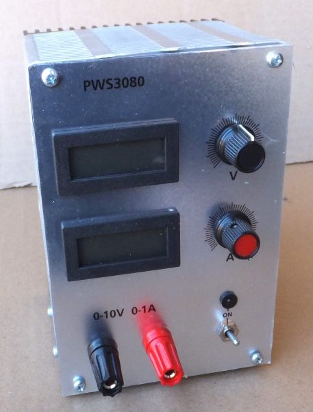
The power supply.
What we have seen so far is enough to build its own power supply to use all 'inside of other devices, but, given that the' whole seems to work just fine, was built a box with accessories minimal.
Built because not founded nothing suitable and, although I accomplishments "mechanical" than ever of just liking, there was no other way. From the photos we can see precisely processing unprofessional metal.
The front panel, in the absence of 'photo sensitized aluminum, was done with a plastic sheet (KPS) from laser printer then treated with a spray protection
(Letraset)
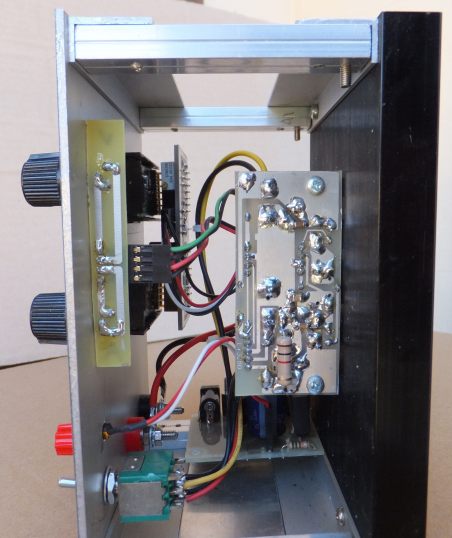 |
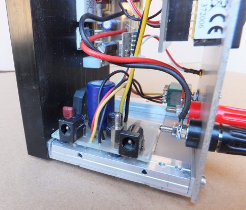
Side view with out the solder side of the main printed circuit board and the support of the
potentiometers.
The first note is the 1K resistor of minimum load, welded on this side (just because from 'the other hand made it difficult to get to the screw of the support
square).
The potentiometers need a cs support for two reasons: to make easy to assemble the everything in the container and, above all, to avoid mechanical tension on the pins of the potentiometers themselves, which are, at least for the model used, of small cross section and can break with
ease.
As usual, the printed stagnated cold to prevent corrosion of the copper over time.
L 'on / off switch is a three-way only because I had this type
available.
The front panel LEDs receives the 'power from the circuit board supporting the
rectifier.
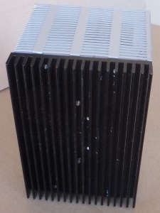
|
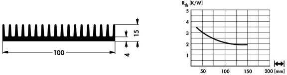
The construction is based on a heat sink of the kind of the Fischer SK81 from 100x145 around which the box is made, with elements of aluminum of
Alfer, which can be found in some
Brico.
The heat sink is critical, since, as we have mentioned, linear regulators Warm according to their voltage drop.
 |
The chosen one is more than sufficient, taking into account the fact that the 'coupling-integrated heat sink is much worse by the need to isolate the tab, that are connected to the OUT pin.
As mentioned, the tab of the integrated is connected to a pin active and so you need to isolate them from the heat sink, with pad in mica and conductive thermal
compound.
The choice of model is due to the fact that I in the laboratory some pieces and that its shape lent itself well to occupy the rear side of the box.
|
Obviously goes well any other type of construction and a sink with proper thermal
resistance.
The PCB of the '"central unit" is fixed to the heat sink and supported by integrated, but this is not enough, as it downloads any mechanical stress and vibration on the same pin. To give sufficient mechanical strength added two squares in nylon.
Main power.
 |
The primary power is delivered from any wall plug with output at full load> 12V. This choice
allows:
- to have a smaller unit that if it were to contain the transformer
- does not bring the mains voltage to 'internal' s apparatus
- and, quite important, at least for applications with which you may have to do, it can be powered with a battery, making the system completely separate from the network, which is very useful in
testing.
|
The supply voltage required is found to be at least 12V If you want an output from 0-10V. In fact must be considered that every LT has its own fall minimum of about 350mV, in addition to that of 1V on the Rs, which are needed for safety for a minimum of 2 volts above the maximum voltage that you want to output.
Certainly also go well more, within the limits of 'integrated, for example 20V, but
it must be remembered that the dissipation of heat will be greater the greater is the difference between the input voltage and output voltage, requiring a cooling system very cumbersome .
So, even if possible, it is not advisable to exceed 15-16V to avoid unnecessary heating.
In any case, the LT3080 has an internal protection against over temperature, which should prevent their damage, though, as usual, is not a good idea to count on this project except in cases of
emergency.
If you have a transformer, it will follow the usual Graetz bridge and a 2200 uF electrolytic kind.
In the embodiment it has been inserted a small printed with the bridge and the capacitor, in addition to a socket for a signaling LED
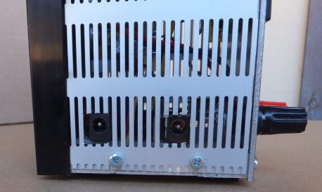 |
The access is made with the usual coaxial plug.
And there are two, one upstream from the bridge to an AC input and one downstream for a DC input, for a battery supply.
A 2A fuse has been inserted for the safety of all.
A switch on the front two-way needed for the on / off. |
The small printed located at the base of the container, isolated with two washers of the kind used for the transistors in TO-3
Instruments.
They could not miss the voltmeter and ammeter. Rather than using the usual microcontroller with an LCD display, I chose two classical woodwind instruments panel.
 |
Are 45x22mm LCD, 3 1/2 digit with the usual scale of 199.9 mV; they are also more than affordable prices, such as the DVM210 to € 8.61 or less
(Conrad)
.
Used here are of DPM-951R
|
The schematic:
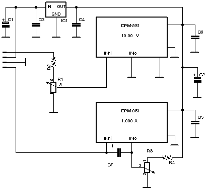 |
IC1 78L05
C3/4/5/6 100nF
C7
10nF
C1 100uF-25V
C2
47uF-10V
R2
R1
10giri
R4
867k
R3
100k-10giri
|
To avoid complicated wiring and not very pleasing, it has been realized a printed circuit support, in which the instruments are inserted exploiting their connector CN1.
 |
Side view of the tool holder.
The two instruments are plugged in a small printed circuit board which carries the resistance and trimmer
necessary.
In view, that of zero for the current measurement.
On the same printed it is also mounted the regulator 78L05.
|
Resistors and ceramic capacitors are SMD, where it is available a wide range of values and that occupy very little space, are welded on the side opposite to that of the components in the hole, making it very compact the
whole.
 |
For voltage measurement, taken from the output terminals, is inserted a divider (1: 100) in order to have 100mV to 10V input. The instrument will then 10:00.
Not having a divider resistors Decade resistors also outside the series and not easy to find at reasonable cost, it used a divider with R1 trimmer to fine tune the full scale.
Here it is used a 10-turn, however, is not having it, you can use the one from the first round (of good quality anyway) by inserting it between two resistors calculated to obtain the highest resolution on the turn of the
cursor. |
To measure the current could be considered unnecessary to add a shunt, since there is already the R6 from 1 ohm. The problem is that it is located upstream of the voltage regulator and therefore it is always crossed by a current, which varies with the output voltage. Furthermore, the used one is quite inaccurate to become a shunt to measure the current.
So it was necessary to add a resistor to the minimum value on the positive side of 'output. In these conditions, the measuring instrument, which can operate as a differential, to read the voltage across the shunt must have a separate power supply. To avoid this, the two instruments are powered by a single regulator gender 78L05, which reduces derived from the input voltage of the 'power supply, while the current signal is produced from a high side current monitor, gender MAX4372.
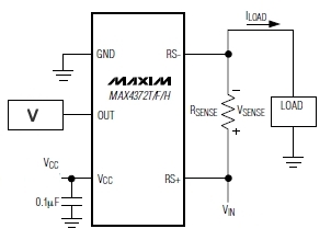 |
This is a differential amplifier which makes a voltage output proportional to the voltage drop measured on Rsense.
It exists in three versions with different gain:
The voltage at the OUT pin is:
Vout = ILoad * Rsense * gain.
Having available a Rsense from 5 milliohms, with the version T is obtained an output 100mv for a current of 1A. With the F version will have the same output on a Rsense 2
milliohms. |
The current sensor has been realized on a sub-printed circuit board which is plugged into the main printed on a connector of the controller.
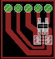 |
Unfortunately, the MAX4372, as most of the components of the last generations, does not exist in packages for mounting on the hole, but only as SMD. In fact it is a small SOT23-5.
It is therefore necessary to make a small circuit quite accurate. But it is a simple extra circuit, comprising only the MAX4372, the capacitor and the connector 2.54. For convenience, given the small size, it was inscribed on a slab with thickness 0.8mm. |
In the picture below, we see him next to the resistance measurement of the
current.
This can be realized with a circuit trace, but, having available shunt resistors of suitable values, it is preferable to use those. The Rsense printed on has no cost, but it is not easy to get the right value, since it depends on a certain precision in size, not easy to make at home. It can, however, just make a little bigger track (lower resistance) and then "calibrate" by cutting off the strips to increase its value, but it is a tedious task. Or you can leave a slightly greater value and adjust the tension to 'input of the instrument, similar to the voltmeter.
From the point of view of accuracy of the measurement should be borne in mind that the copper has a coefficient of temperature sensitive and the resistance change as a function of temperature, which in applications "series" can not be tolerated (although here may be
adequate).
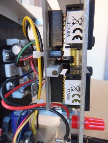
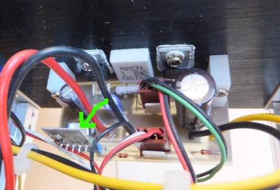 |
R6, indicated by the green arrow, is a bridge of metal calibrated.
If they can recover strengths such as PC power supplies that have a serious protection against ctocto and Surge;
commercially they are easily found and have an exaggerated cost. Who likes to do everything by itself, it can derive a similar resistance from a few conductor of a heating element, a shunt of an old meter and the
like.
If for very low value, type 1 milliohms, will be offset by 'use of MAX4372H, gain 100.
|
Next to the R6 we see the sub-printed of the current sensor.
From the picture we see also the R5 and R6 and the two LT3080 isolated from the heat sink. Part of the connections is made with connectors, 2.54 to facilitate testing and to make possible the mounting in the
housing.
Obviously the Rsense in series adds a voltage drop which is not compensated for by the controller (it would be possible, given that the 'integrated is floating, provided with a discrete complication, for example with the' addition of a pair of operational, but this solution It is not considered as it is in conflict with the 'primary idea to create a collection as simple as possible). It is, however, a minimum fall: with 5 milliohms, you will have 5 millivolts in less than the maximum current, which is not perceived by the instrument voltage measurement; it is not the best, since LT3080 exhibited a phenomenal adjustment to three decimal places. However, even so the stability of 'output is comparable to that of circuits far more
"noble".
 |
In practice, the current sensor has a certain offset voltage which prevents the instrument for measuring the current of 0.000 indicate when there is no load. It is necessary to remove this offset, which is possible by adding some components.
But there is an easier way: the tools that are based on 'ICL7106 or clones have differential input (INHI and
INLO).
To offset the 'offset, simply assign a value equal to INLO, with a divider (R3-R4) in which a multi-turn trimmer allows you to fine tune the desired tension. If the 10 laps there, you may use the solution indicated
previously. |
Not wanting to introduce a precision voltage reference, it was used the same supply voltage of the instruments: the 78L05 works with a minimum load (about ten milliamperes), essentially constant, so it provides a stability from sufficient for the 'application.
The printed circuit boards of the rectifier, support tools and potentiometers are entirely too trivial and for the components used; those who want to replicate them, probably will in a different form and it will be easy to achieve the necessary
printed.
Espansions?
Since the component allows input voltages greater than 12V, it would be possible to realize a different version, for example up to 20V, feeding all at 23-24V (the maximum supported by the current monitor is 28V).
Therefore it will be necessary to change the value of the potentiometer connected to pin September
It goes without serving exhaustively a radiating surface much greater to dissipate the heat that occurs with the greatest fall on the regulator, which is linear. A significant improvement would occur using separate radiators for both LT and eliminating the 'isolation.
A similar circuitry is achievable even with LT3083 that allows a current of 3A. Here, too, it will be a requirement sink of adequate
size.
Conclusions.
The noise output is actually negligible.
Stability with the load is the parameter that was more surprising (to three decimal places!) And with variations of line is
imperceptible.
This component, although not economicissimo and not immediate to find, it seemed an object that keeps its promises and is not particularly difficult to use, always on condition of a wiring not messy and use of components of equally good quality
.
Where necessary something more refined of the old LM317, can be seriously considered. LT3080, as LDO, it is excellent in voltage power supplies fixed or adjustable in a certain range, even with input voltages really very close to the outlet port; l 'use of capacitors of low capacity reduces the size of the whole.
It might be reasonable to retire the various LM317 and 7805 in many applications.
|